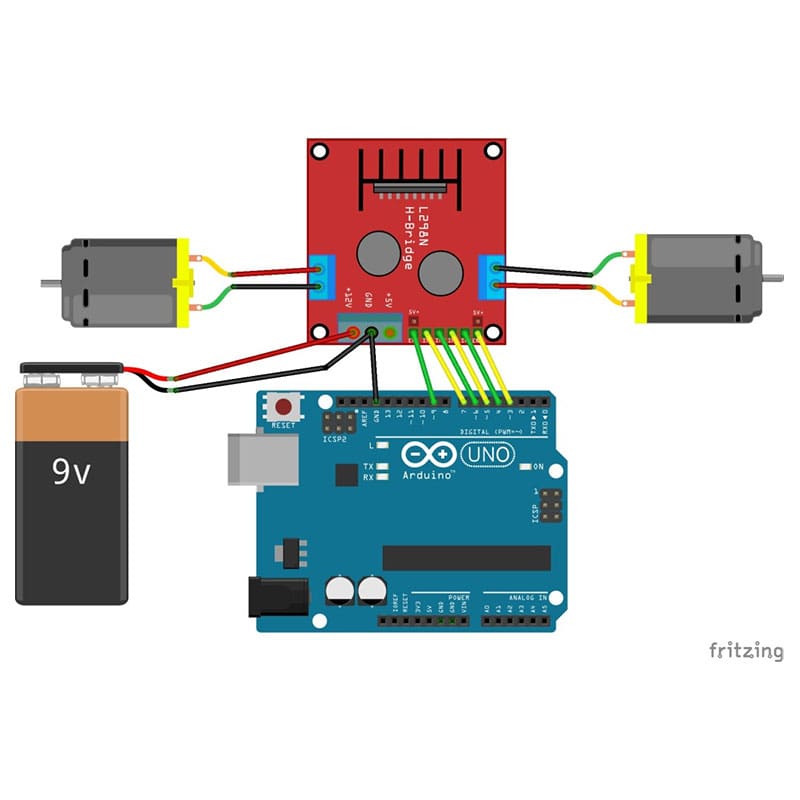

Controlling level: Low -0.3V~1.5V, high: 2.3V~Vss.Logic power output Vss: +5~+7V (internal supply +5V).An additional supply input is provided so that the logic works at a lower voltage. The emitters of the lower transistors of each bridge are connected together and the corresponding external terminal can be used for the con-nection of an external sensing resistor. Two enable inputs are provided to enable or disable the device independently of the input signals. It is a high voltage, high current dual full-bridge driver designed to accept standard TTL logic levels and drive inductive loads such as relays, solenoids, DC and stepping motors. Scroll to continue with content.Double H driver module uses ST L298N dual full-bridge driver, an integrated monolithic circuit in a 15- lead Multiwatt and PowerSO20 packages. The L298N Dual H-Bridge Motor Controller is an inexpensive device that allows you to control two independent DC motors using 5-volt digital logic signals, such as the digital output pins of an Arduino.As for the power supply, I chose to use three 3. You need few additional components for this project and the complete list is given below.
#L298N MOTOR DRIVER CIRCUIT DIAGRAM HOW TO#
How To Make a DC Motor Speed Controller using Arduino and L298 Motor Driver. The Arduino generates control signals based on the input from the variable resistor but the motor can not process them directly so we are using an L298N motor driver. The module can drive DC motors that have voltages between 4. DC motor 2 "-" or stepper motor B- Controlling DC Motors To control one or two DC motors is quite easy.
#L298N MOTOR DRIVER CIRCUIT DIAGRAM CODE#
Step by step wiring, code and demonstration displayed.


DC motor speed control Arduino code Below is arduino code for DC motor speed and direction control using L298D motor driver.

Robojax ESP8266 DC Motor HTML page and Arduino code and.


 0 kommentar(er)
